From geometry to manufacture.
NX CAM, production definition and inspection
Two connected manufacturing studies: optimise the toolpath for an aluminium plate, then define a separate component so it can be made and inspected.
Validate the toolpath
I created face-milling and hole-making operations in NX and checked cutting distance, non-cutting travel, machining time and material removal with hand calculations. The comparison kept the main validation differences within the assignment’s 10% range.
Change a parameter, understand the effect
The simulated face-milling cycle fell from 82 seconds to 70 seconds when the feed rate increased to 6,000 mm/min. Increasing spindle speed alone did not change the programmed path or cycle time. Reducing step-over from 75% to 50% increased the number of passes and the total time to 113 seconds.
Connect design intent to inspection
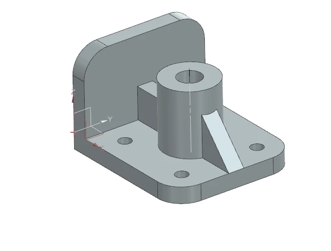
For the production component, I developed a drawing and 3D PMI model with a datum system, tolerances, surface-finish requirements and GD&T. I then proposed suitable measurement equipment and an inspection sequence based on those requirements.
Choose a manufacturing route
I compared subtractive machining, additive manufacture and injection moulding. CNC machining suited the defined final component, while printing offered a route for prototype evaluation. The CAM work produced post-processed machine code, but the report does not claim a physically machined production run.
1 / 6 · Select image to enlarge
A 3D PMI view communicating the component’s dimensional and geometric requirements.
Project evidence: CAM/CNC Machining Tool Path Optimization and Methods of Measurement report dated 29 March 2026. Timings are CAM estimates, not shop-floor measurements.
Stiffness with a constraint.