Motion, understood.
Slider-crank mechanism analysis
A 110 mm crank and 340 mm connecting rod, examined through CAD, numerical simulation and independent analytical calculations.
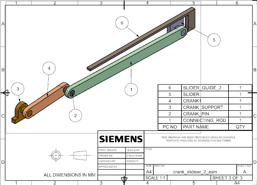
Build the motion model
I modelled and assembled the mechanism in Siemens NX, then defined its revolute and translational joints. The analysis used a constant crank speed of 4 rad/s over five full revolutions.
Check the software with the equations
I derived position, velocity and acceleration for the crank pin and slider, evaluated the equations in Excel and compared them with ANSYS Rigid Dynamics outputs. This provided an independent check on the simulation rather than relying on its animation alone.
Resolve the differences
Extracting reliable higher-order motion outputs required moving from the initial NX motion setup to ANSYS. I aligned coordinate directions and reference datums before comparing curves. The report describes close agreement, with small peak differences associated with discretisation and rounding.
What the geometry explains
The finite connecting-rod length makes slider motion depart from a pure sine wave. It produces sharper acceleration peaks near the ends of travel. The interactive diagram below uses the project’s 110:340 length ratio to make that relationship visible.
Explore the motion
Move the crank and see how rotation becomes linear travel. Geometry scaled from the project: 110 mm crank and 340 mm connecting rod.
1 / 4 · Select image to enlarge
Connecting-rod manufacturing drawing from the NX model.
CAD motion study
The original NX screen recording shows the assembly moving through its constrained motion. Quantitative comparison in the report uses ANSYS Rigid Dynamics and Excel.
Project evidence: Motion Analysis of a Typical Crank-Slider Mechanism report dated 18 April 2026, original drawings, analysis plots and CAD recording.
From geometry to manufacture.